
When I am investigating something new, I like to try and imagine an ideal application for whatever it is I am investigating. This project grew out of one of these brainstorms. I was evaluating some capacitive sensors for work and was impressed at the range at which it could sense things. If I could move the sensor in a controlled manner, I could produce images representing the capacitance of an object.
Electronics
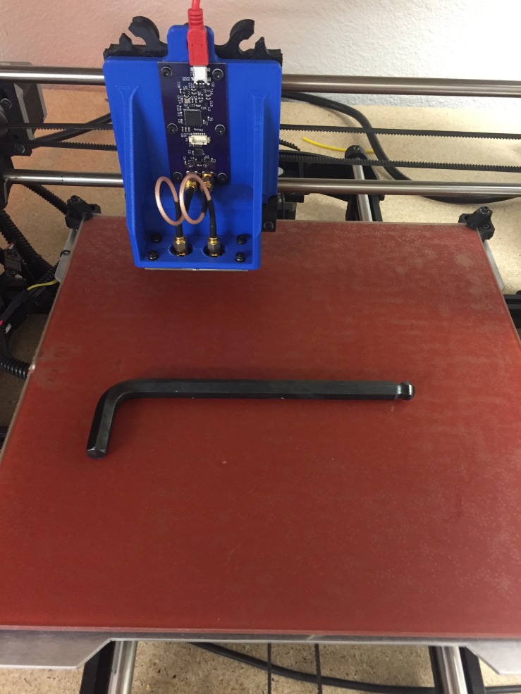
I drew up a board and created a mounting bracket so that it would fit into my 3d printer. The sensor is an FDC2212 mated to a MSP430F5528. I followed the TI evaluation module example close enough to make use of their example firmware with minor changes.


First scans
I knew that temperature would be a factor but didn’t realize just how important it would be. Both the air and the electronics themselves are effected by the temperature. My first scan looked like the following


The dark spots are artifacts of the filtering. Luckily I anticipated the temperature dependence and placed an I2C port on the main sensing PCB for additional sensors.

Future goals
In the coming weeks I’m planning on working on the following:
- Adding a temperature sensor to the I2C port
- Calibrate for temperature drift
- Develop more image processing tools
- DFT analysis for easier filtering
- High and low pass digital filters
- Adding a time of flight sensor to the I2C port
- Add inductive sensing
- Make a larger sensing element
- Make a circular sensing element
- Improve the sensitivity by removing/improving the shield drivers on the coax cables
- Evaluate scanning speed
- Faster= better for temperature drift
- Too fast = smearing

[…] create with it. With a little imagination you can turn your machine into a 3D scanner, and using capacitive sensors to image items turns out to be an interesting […]
LikeLike
Very cool idea Nelson!
I just had a read of your python code, it’s very elegant and nicely thought out.
If you were after a more dramatic sample target, maybe something with more water content, or non metallic? If you had a large block of plastic, you could drill or cut regions out from underneath, but leave a pristine surface on top. Once scanned, the hidden message would be revealed.
I made a low-energy ‘single pixel’ CT scanner a while ago (have’t blogged it yet, but very similar to http://www.tricorderproject.org/blog/tag/openct/) and one thing I always wanted to do was add in a lot more sensors. My wish list was something like distance sensor (measure to top surface of object), plus spectral/RGB optical data, as well as inductive and capacitive sensing. (Hell, if you’re spending time mechanically scanning over a plane or volume anyway, why _not_ cram in as many sensors as possible on the moving head).
Of course dealing with a huge multispectral data set is _much_ more complicated, but that’s one of those problems that’s wonderful to have 🙂
LikeLike
Thanks for the feedback!
That CT scanner is impressive! Where do you post to?/Drop me a line if you ever write it up.
I like the acrylic idea. Some dielectric type scans are definitely on the todo list, but first I wasted to get the temperature sensor integrated so I don’t have to filter as heavily.
LikeLike
I don’t know if this is practical for you but why not slightly heat the whole device in a container and give it a negative feedback loop thermostat to lock in on a temperature and eliminate almost all of the variability? That might serve you. 🙂
LikeLike
I think the main issue with the room thermostat is the bang/bang controls. I might need a thermopile or some other “analog” type heater to hold the enclosure at a precise temperature
LikeLike